Many 'long wire' antenna installations benefit from an ATU located close to the feedpoint. However, the feedpoint is often best situated some distance from the radio 'shack'. This raises the question of how to power the ATU. This article provides one possible solution.
Chèz G0XAN the inverted-L longwire antenna is fed at the far end of the garden via an LDG Z11pro auto-ATU in the garage. There is no mains power in the garage and the Z11pro requires 12V to operate. It consumes almost no power in 'sleep' mode so can operate for several years on a set of alkaline AA batteries.
The problem with batteries is that they don't really like the cold and damp of the garage and without some means of monitoring them it's impossible to know what state they're in. The Z11pro requires only 300mA whilst tuning and will operate down to about 8V so providing 12V DC from the 'shack' is a possibility.
Running an extra DC cable from the 'shack' to the garage seemed like an unnecessary complexity, and Google came to the rescue with a circuit to feed DC power via the RF co-ax by Phil Salas, AD5X.
Phil's article describes the circuits in detail: http://www.ad5x.com/images/Articles/RemoteDC%20RevA.pdf
Phil shows two separate circuits, one to inject DC into the cable and another to recover the DC. There are only two small differences between the two circuits; the injection circuit is fused and has a diode to protect against reverse voltage; the recovery circuit is unfused and has a 15V zener diode to protect against overvoltage spikes. I decided to make two identical circuits using a fuse and zener diode at each end. The fuse at the recovery end is probably redundant but it does mean that it doesn't matter if the boxes are swapped over at some point.
The circuits were built on scraps of perforated board. Veroboard, matrix board or tag strip could be used. The circuit probably doesn't warrant a PCB design.
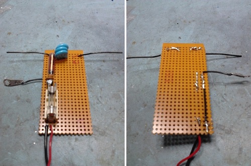
The red and black wires at the bottom are the DC connection, the black wires at the top connect to the SO-239 sockets, and the ring terminal connects to the body of one of the SO-239 sockets and the case. The DC 0V is connected to the co-ax outer and the metal case.
The board was designed to fit into a small diecast box. It's difficult to see in the photo but a piece of 3mm polycarbonate was cut to fit in the bottom of the box to insulate the connections on the underside of the board from the box.
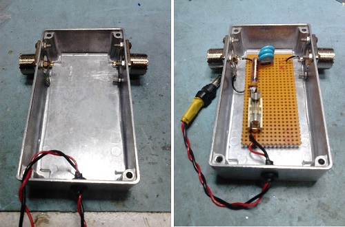
The DC power wires are fed through a grommet and terminated in a suitable connector. There is plenty of space in the box to fit a suitable DC connector if required.
UK Parts List
The original article provides a comprehensive parts list, but the JW Miller (now part of Bourns) inductors are not easy to obtain in the UK. I managed to find some slightly different inductors with a better specification manufactured by Epcos and stocked by Rapid Electronics.
| Description | Rapid Part Number | Quantity |
| Diecast Box 111x60x30mm | 30-3650 | 1 |
| SO-239 Socket | 16-0150 | 2 |
| Epcos B82111EC25 100uH 1A Inductor | 51-7607 | 1 |
| Murata 10nF 2kV Capacitor | 08-1524 | 3 |
| 4.7uF Electrolytic Capacitor | 11-3502 | 1 |
| 100nF Ceramic Capacitor | 08-0235 | 1 |
| 10nF Ceramic Capacitor | 08-0232 | 1 |
| BZX85C15 15V 1.3W Zener Diode | 47-3078 | 1 |
| 500mA Fuse | 54-3143 | 1 |
| 20x5mm Fuse Holder | 26-0165 | 1 |
The datasheet for the Epcos inductor shows that it provides over 1000 Ohms impedance from 1.8MHz to 55MHz. Note that the inductor is only rated at 1A DC so this (in addition to the fuse rating) limits the amount of power that can be delivered to the load.
Another consideration is the DC resistance of the co-ax. 30m of RG58 has a DC resistance of less than 2 Ohms (total). This is OK for a DC load of a few hundred mA, but a longer run and/or higher current may result in a significant voltage drop.