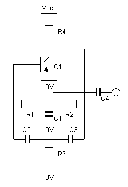
The Twin-T oscillator is a simple, reliable oscillator that gives a sinusiodal output without the need for a negative-resistance element to stabilise it. It runs happily off of a range of supply voltages and can be built around almost any NPN or PNP trnasistor, or around an op-amp. It makes a nice sidetone oscillator for a CW transmitter, or a very good Morse practice oscillator. It can also be used as the basis of a two-tone oscillator for testing SSB transmitters.

R1 = R2 = 10 x R3, C3 = C2 = 2 x C1
I am not sure of the calculations required to determine the values of R1-3 and C1-3, but below are the values that I have successfully tried, and the frequencies that they give. For the circuit to work reliably the ratios shown above should be used.
| R1 | R2 | R3 | C1 | C2 | C3 | Frequency |
| 18k | 18k | 1k5 | 47n | 22n | 22n | 700Hz |
| 22k | 22k | 2k2 | 22n | 10n | 10n | 1200Hz |
The output of this circuit should be fed into a high-impedance load, say >100K, remembering that the impedance of C4 is around 3K.
A PNP transistor can also be used, with the necessary changes to the supply voltage. An op-amp can also be used, connected as follows:
| Op-Amp | Transistor |
| Output | Collector |
| Inverting Input | Base |
| Non-inverting Input | Emitter |
Circuit layout is not particularly critical. The circuit can be constructed on Veroboard, built "ugly-style" on a scrap of copper-clad board, or incorporated into a PCB design for a larger project.