This article describes the construction of a lightweight, ultra-portable 5-element beam antenna for 2m. It provides useful gain and front-to-back ratio whilst packing down to a very portable metre-long package. It is quick and easy to deploy; it is possible to set it up single-handed in less than 15 minutes.
The antenna is based on a design by DK7ZB. All the dimensions are specified on his website so will not be repeated here. This article covers my implementation of the design with an emphasis on making a light, portable antenna.
I wanted to build a 2m beam that was cheap, very lightweight, easy to assemble in the field, and easy to carry in a rucsac or on a bicycle. As I live in something of a VHF black hole, I have to go out portable on the local hills to do any VHF operating.
The DK7ZB design fitted my requirements almost perfectly, although I wanted something that would pack down slightly better, ideally to a metre long. I figured I could do this with a 5-element beam, rather than taking the easy way out and using a 3-element design :-)
By splitting the beam at the driven element I could reduce the longest part to just over a metre long. By fitting the elements through the beam I got rid of the saddle clamps on the elements, meaning that the elements could be packed inside the boom.
Materials
All of the materials were sourced from local DIY and model shops, apart from a few odd screws etc that came from my "junk box".
- 20mm electrical conduit, available in 2m or 3m lengths from most DIY stores or electrical wholesalers.
- Throughbox to fit conduit, available from B&Q or electrical wholesalers.
- Conduit spacer bar saddles, available in packs of 5 or 10 from most DIY stores or electrical wholesalers.
- 30A terminal block, available in strips of 12 from most DIY stores.
- 4mm aluminium rods, available in 1m lengths from B&Q or specialist metal suppliers.
- 8mm fibreglass kite spar, available from specialist kite shops.
- 3/16" brass or aluminium thin-wall tube, available in 12" lengths from most model shops.
- 5/32" brass rod, available in 12" lengths from most model shops.
- M2 x 6mm screws.
- Small ring tags, suitable for M2 screws.
- 0.4m 50-Ohm co-ax. I used RG-174 as I had some to hand.
- BNC socket (or any other type that you prefer).
The Build
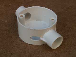
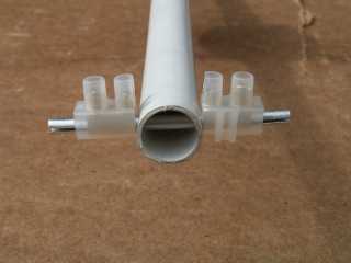
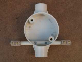
The centre of the dipole is built into a conduit throughbox (in-line junction box). This picture shows the completed assembly; the parts are explained below. 30A terminal block is used to clamp the 4mm aluminium dipole elements in place.
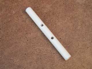
The centre insulator for the dipole is made from a piece of 8mm fibreglass kite spar. The spar is hollow, but needs to be drilled out to 5mm to accept the tubes that hold the elements. The tube is about 70mm long, with 3mm holes drilled 20mm apart at the centre.
The junction box is drilled to take the fibreglass tube. The tube must be aligned with the centre-line of the conduit, and at right-angles to the conduit. I drilled the holes slightly oversize and used epoxy to hold the tube in the correct place.
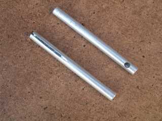
Two pieces of 3/16" aluminium tube are used to hold the dipole elements. A 3mm hole is drilled 5mm from one end, and a slot 20mm long is cut in the other end. The slot is cut on the opposite side to the hole so that the terminal block screws bear on the solid side of the tube and not on the slot. 4.5mm aluminium or brass tube could be used, but imperial sizes are commonly available in model shops.
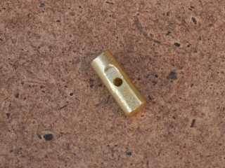
Two pieces of 5/32" brass rod, 10mm long are used to make the electrical connections to the dipole. An M2 tapped hole is drilled 5mm from the end. A small flat is filed on the rod to make it easier to drill. Use a 1.7mm pilot drill for the M2 tap - it saves on broken taps and drills! 4mm brass rod could be used, but imperial sizes are commonly available in model shops.
Assemble the brass rods into the aluminium tubes and line up the tapped holes with the clearance holes in the tube. The rod is a reasonably good fit in the tube and should stay in place if the assembly is handled carefully. Once assembly is complete, everything is screwed together and there is no problem. Next, insert the tubes into the fibreglass tube and line the holes up. This gives the required 10mm gap in the middle of the dipole. M2 screws secure the ring terminals for the co-ax balun (not shown). Slide a piece of 30A terminal strip over the aluminium tube. Do not tighten the screws too much, otherwise the tube will be crushed and the dipole element will not go into it!
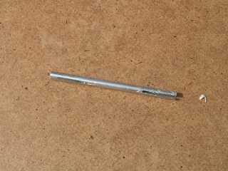
The reflector has to be 1036mm long,and the aluminium rods available at B&Q are only sold in 1m lengths. To overcome this problem, I made an extension piece to go in the centre of the reflector. A 75mm long piece of aluminium tube is slotted 20mm at each end. Into this tube insert a 38mm piece of 4mm aluminium rod, cut from the left-overs from the directors. Don't cut this piece to exactly 36mm, as when you cut a 1m piece in half, you will not get two pieces 500mm long! Best to cut the centre slightly oversize and then file the other pieces to the correct length (499mm). A piece of 30A terminal strip at each end holds the element pieces in place.
The reflector centre piece is fitted into a 5mm hole through the end of the boom. A piece of 30A terminal strip at each end holds the element pieces in place. The inner screws hold the centre piece in place on the boom, the outer screws secure the element pieces.
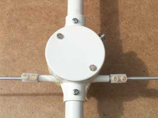
The dipole centre is fixed to two pieces of 20mm conduit which form the boom. One piece is about 300mm long and holds the reflector, the other is about 1m long and holds the three directors. A self-tapping screw secures each boom piece so they are correctly aligned with the dipole. A quarter-wave balun is wound inside the junction box - about 5 turns of RG-174 co-ax on a piece of 20mm conduit. A BNC socket is fitted to the junction box (just visible back-right).
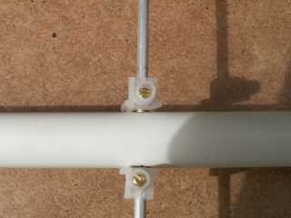
The directors are fixed through the boom. They are quite a good push-fit in a 4mm hole, but I added some 30A terminal blocks to keep the elements in place. After a while I expect the holes to have enlarged somewhat; the terminal blocks will ensure they stay in the right place. I sawed the terminals in half as only one screw is needed to hold the elements. It makes the elements slightly less bulky.
The plastic was removed from one of the terminal blocks and the element and terminal block were painted with some spare spray paint I had lying around. The paint fixes the screw in place so the element is in the right position every time it is fitted through the boom. The boom was also painted around each director hole. Each director is painted a different colour, so that it is easy to put the elements in the correct holes without having to measure them each time!
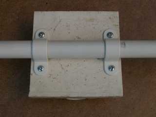
The boom is fixed to the mast using conduit saddle clamps. The conduit may need a couple of turns of insulating tape to make a snug fit in the clamps. The clamps are fixed to a 100mm square of plastic using self-tapping screws. On the other side of the boom two clamps are fitted at right-angles to these. With a bit of rubber sheet or
Dycem packing, the saddle clamps fit nicely on a fishing pole at about 4m high. I drilled the clamps out to take 4mm screws and wing nuts instead of the small self-tapping screws supplied as standard. This makes life easier in the field with fewer small parts to drop and fewer tools needed. The boom can easily be rotated in the clamps to change from horizontal to vertical polarisation, simply by loosening four screws.
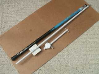
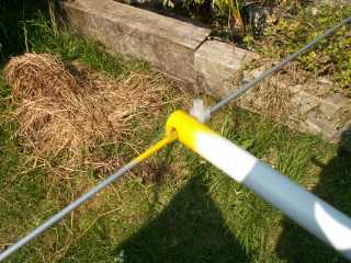
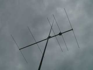
The complete antenna packs down to two sections. All the elements fit inside the main part of the boom. The dipole centre is attached to the shorter part of the boom which has the reflector centre at the end. The antenna is conveniently mounted at 4m on a 7m fishing pole. With the mast the whole system weighs around two kilos.
The complete antenna at 4m on the fishing pole mast.
This antenna has proved itself in several excursions onto the South Downs, mostly to take part in the RSGB Backpackers' contests. Using 2.5W from an FT-817 we have regularly contacted stations several hundred km distant. The front-to-back ratio seems good, providing noticeable attenuation of strong local signals. Most importantly the antenna is rugged, reliable, easy to assemble and light and easy to carry.